Contents
- 1 Basic Kubota Front End Loader Hydraulic Line Diagram
- 2 What Each Hydraulic Line Does
- 3 Boom and Bucket Cylinder Lines
- 4 Common Kubota Loader Valve Hose Routing
- 5 Signs the Hydraulic Lines Are Connected Wrong
- 6 Safety Tips Before Working on Loader Hydraulic Lines
- 7 How to Label Kubota Loader Hydraulic Hoses
If you are searching for a control valve diagram for Kubota front end loader hydraulic lines, you are probably trying to figure out where each hose goes: pressure, tank, power beyond, boom lift, boom lower, bucket curl, and bucket dump. That confusion is very common, especially when a loader has been removed, a valve has been replaced, or the hydraulic hoses were disconnected without labels.
Kubota loader plumbing can vary by tractor model, loader model, and valve type, but most front end loader hydraulic systems follow the same basic layout. Understanding the port names and hose routing will help you read the diagram correctly and avoid expensive hydraulic damage.
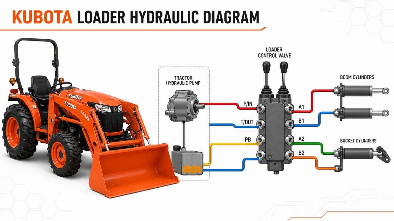
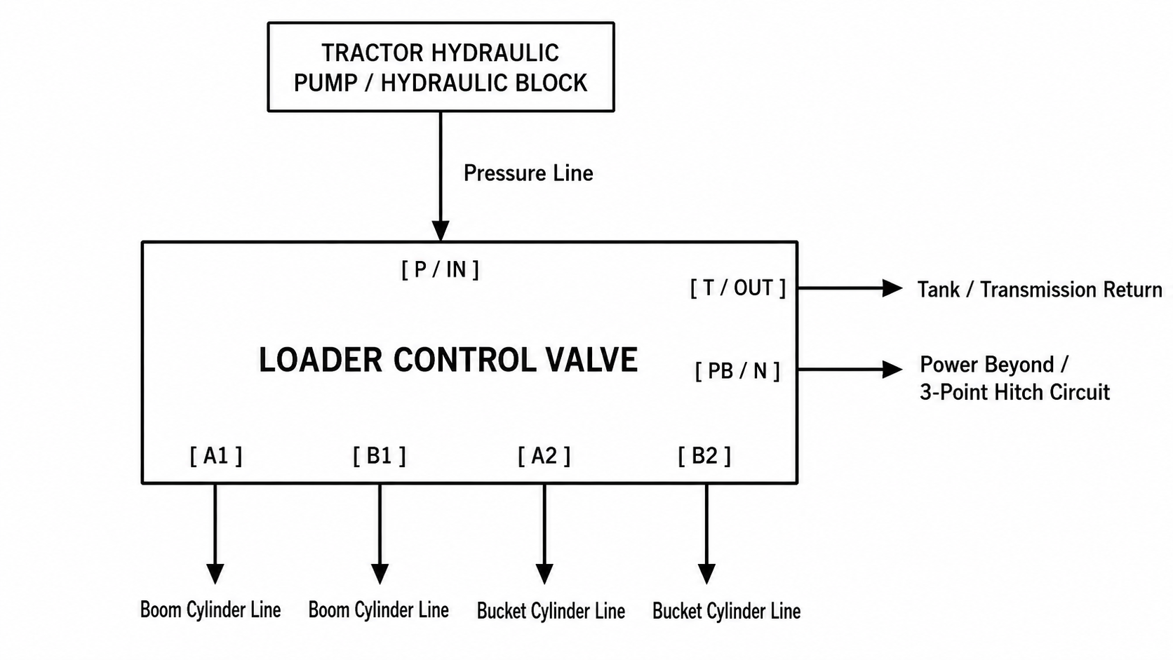
Basic Kubota Front End Loader Hydraulic Line Diagram
A typical Kubota front end loader control valve has these main ports:
| Valve Port | Common Label | What It Does |
|---|---|---|
| Pressure In | P / IN | Brings oil from the tractor hydraulic pump or hydraulic block |
| Tank Return | T / OUT | Sends return oil back to the transmission case or tank |
| Power Beyond | PB / N | Sends pressurized flow downstream to the 3-point hitch or rear hydraulic circuit |
| Boom Work Port 1 | A1 | Sends oil to one side of the lift cylinders |
| Boom Work Port 2 | B1 | Sends oil to the other side of the lift cylinders |
| Bucket Work Port 1 | A2 | Sends oil to one side of the bucket cylinders |
| Bucket Work Port 2 | B2 | Sends oil to the other side of the bucket cylinders |
A simplified loader valve diagram
In many Kubota loader setups, the P port receives pump pressure, the T port returns oil to tank, and the PB port feeds the hydraulic circuit downstream, often the 3-point hitch. A Kubota loader workshop manual description for LA-series loaders explains that the P port connects to the hydraulic block outlet, the T port connects to the tank port, and the PB port feeds oil back toward the tractor hydraulic block/3-point control circuit. (Scribd)
What Each Hydraulic Line Does
1. Pressure Line
The pressure line carries hydraulic oil from the tractor pump or hydraulic block to the loader valve. This line usually connects to the port marked P, IN, or Pressure.
If this hose is connected incorrectly, the loader may not move, the 3-point hitch may stop working, or the hydraulic system may deadhead and overheat.
2. Tank Return Line
The tank line sends return oil from the loader valve back to the tractor transmission case or hydraulic reservoir. This line usually connects to the T, OUT, or Tank port.
Do not confuse the tank port with the power beyond port. The tank line is not designed to carry full downstream pressure. Connecting it incorrectly can damage seals or valve components.
3. Power Beyond Line
The power beyond line is one of the most misunderstood hydraulic lines on a Kubota loader. It carries pressurized oil from the loader valve to the next hydraulic function downstream, often the rear hydraulic system or 3-point hitch.
Land Pride’s Kubota LX2620 third-function installation manual specifically warns that improper connections to the power beyond port and return to tank port can cause serious tractor damage. (Great Plains Mfg)
In simple terms:
- Pressure line feeds the loader valve.
- Tank line returns used oil to the reservoir.
- Power beyond line sends pressure onward to another valve or the 3-point hitch.
Boom and Bucket Cylinder Lines
The four work ports control the loader movement.
Boom Lift and Lower Lines
The boom circuit usually uses A1 and B1 ports. These hoses go to the loader lift cylinders. Moving the joystick forward or backward sends oil to one side of the cylinders and returns oil from the other side.
If the boom works backward, the two boom hoses may be reversed.
Bucket Curl and Dump Lines
The bucket circuit usually uses A2 and B2 ports. These hoses run to the bucket cylinders. Moving the joystick left or right curls or dumps the bucket.
If the bucket dumps when it should curl, the two bucket hoses may be reversed.
Common Kubota Loader Valve Hose Routing
Most Kubota front loader hydraulic systems follow this general routing:
P / IN  = From tractor hydraulic pressure outlet
T / OUT = Return to tank or transmission case
PB / N  = Power beyond to rear hydraulic circuit or 3-point hitch

A1 / B1 = Loader boom lift cylinders
A2 / B2 = Bucket curl cylinders
However, the exact port location can change depending on the loader valve. Some valves have ports on the side, some underneath, and some use hard lines before switching to flexible hoses. That is why you should always compare the valve casting marks, loader manual, and hose routing before reconnecting lines.
Signs the Hydraulic Lines Are Connected Wrong
If the Kubota loader hydraulic lines are mixed up, you may notice:
- Loader does not move
- Loader moves in the wrong direction
- Bucket curl and boom lift are swapped
- 3-point hitch stops working
- Hydraulic oil overheats
- Engine loads heavily when valve is centered
- Hoses jump or vibrate
- Hydraulic pump whines
- Seals blow out
- Oil leaks at fittings
If the tractor strains immediately after startup or the hydraulic system gets hot quickly, shut it down and recheck the plumbing.
Safety Tips Before Working on Loader Hydraulic Lines
Hydraulic systems operate under high pressure. A small leak can inject oil under the skin and cause serious injury.
Before disconnecting any hydraulic hose:
- Park the tractor on level ground.
- Lower the loader bucket fully to the ground.
- Shut off the engine.
- Move the joystick in all directions to relieve trapped pressure.
- Wear gloves and eye protection.
- Clean the fittings before opening the system.
- Label each hose before removal.
- Use the correct Kubota manual for your tractor and loader model.
Never use your hand to check for hydraulic leaks. Use cardboard or wood instead.
How to Label Kubota Loader Hydraulic Hoses
Before removing the valve or loader, label every hose:
- Mark pressure line as P
- Mark tank return as T
- Mark power beyond as PB
- Mark boom cylinder hoses as A1/B1
- Mark bucket cylinder hoses as A2/B2
You can use colored zip ties, paint markers, tape labels, or numbered tags. Taking photos before disconnecting the hoses can save a lot of frustration later.
A Kubota front end loader control valve diagram is mainly about understanding flow direction. The pump sends oil into the loader valve through the pressure port. Return oil exits through the tank port. Pressurized flow continues downstream through the power beyond port. The remaining four work ports control the boom and bucket cylinders.
If you are unsure which port is which, do not guess. A wrong connection between pressure, tank, and power beyond can damage the tractor hydraulic system. Always check the loader manual, valve markings, and model-specific hydraulic diagram before starting the tractor.